We all know that in the design of photovoltaic power plants, There are two designs for the layout of solar mounting structure. The left side of the figure below shows the vertical layout, and the picture shows the horizontal layout. Let's take a look at the difference between the two approaches.
The solar bracket layout has a horizontal and vertical shape, which affects the power generation.
From the figure we can see that the vertical layout is easy to install,and the top installation of horizontal installation is more difficult! This affects the construction progress. After discussing with many experts in the industry, I found that horizontal and vertical has too much influence on the power generation! As the world's leading solar bracket manufacturer, with years of production practice experience, CHIKO-solar energy gradually explains this problem. .
1, Blocking front and rear causes power loss of power station
Solar mounting structure array spacing is a very important parameter in the design of the power station. Due to the limitation of land area, the array spacing is generally only considered to be unobstructed for 6 hours on the winter solstice. However, outside of 6 hours, solar irradiance is still sufficient to generate electricity. From the measured data of the photovoltaic power station I obtained, the power generation time of most power stations on the winter solstice day is more than 7 hours, and even in the west can reach 9 hours. (A simple method of judging, the sunshine hours are the length of time of radiation intensity ≥120W/m2, and when the radiation intensity is ≥50W/m2, the inverter can supply power to the grid. Therefore, when the sunshine hours in December are 6h Above, the power generation time must be greater than 6h.)
Conclusion 1: In order to reduce the floor space and increase the installed capacity per unit area, there will be some obstruction in the morning and evening, resulting in loss of power generation. This is particularly true in rooftop distributed PV.
2, Photovoltaic modules have bypass diodes
Hot spot effect: a solar cell component that is shielded in a series branch, Will be used as a load to consume the energy produced by other illuminated solar modules,The shaded solar cell component will heat up at this time.This is the hot spot effect.
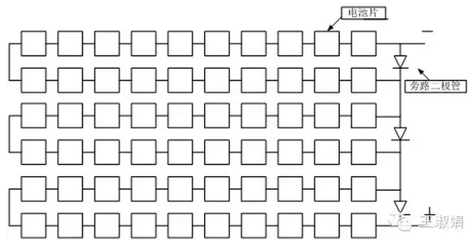
This effect can seriously damage the solar cell. Part of the energy generated by a solar cell with light may be consumed by the obscured battery. In order to prevent the solar cell from being damaged by the hot spot effect, it is preferable to connect a bypass diode between the positive and negative terminals of the solar cell module to prevent the energy generated by the illumination component from being consumed by the shielded component. Therefore, the function of the bypass diode is: when the hot spot effect of the battery chip can not generate electricity, it acts as a bypass, allowing the current generated by other battery cells to flow out from the diode, so that the solar power generation system continues to generate electricity, not because of a certain battery. There is a problem with the chip and the power generation circuit is not available.
The circuit structure diagram of the previous 60-piece PV module.
Conclusion 2: Three bypass diodes are installed in the common PV modules.
3. The effect of the diode on longitudinal occlusion and lateral occlusion.
When the solar mounting structure is arranged in the longitudinal direction, the shadow will block the three battery strings at the same time. If all the three diodes are forward-conducting, the component has no power output. If all the three diodes are not conducting, the power generated by the components will be completely Blocks battery drain and components have no power output.
When the components are arranged laterally, the shadows only block one battery string, and the bypass diodes corresponding to the blocked battery strings are subjected to positive pressure and are turned on. At this time, the power generated by the blocked battery strings is completely blocked by the battery, and the diodes are positive. The guide can prevent the occluded battery from consuming power that is not blocked by the battery string, and the other two battery strings can output power normally.
Conclusion 3: Longitudinal occlusion, 3 strings are affected, 3 strings of output power are reduced; horizontal occlusion, only 1 string is affected, and the other 2 strings work normally.
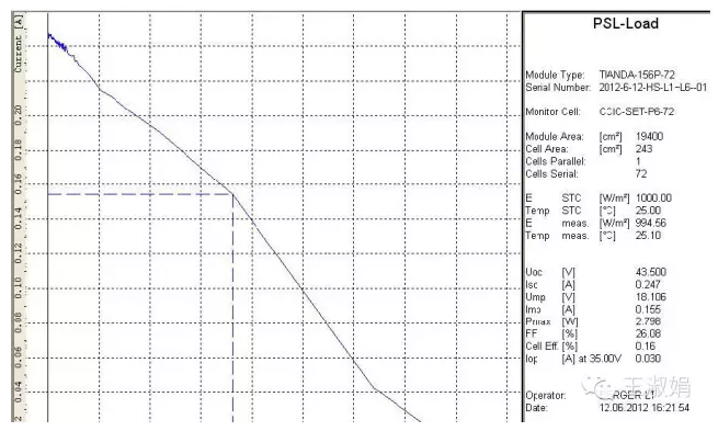
Output test power for unobstructed, longitudinal occlusion, and lateral occlusion under standard test conditions (ie, temperature 25 ° C, spectral distribution AM 1.5, irradiance 1000 W/m 2 ):
Figure 7: The output power of the solar panel when the longitudinal occlusion (Fig. 4 occlusion mode) is as follows
Figure 8: Output power of the solar panel when the horizontal occlusion (Fig. 5 occlusion mode) is as follows
As can be seen from the figure, when the solar panel laterally blocks the battery, the output power of the solar panel is about 2/3 of the normal output power, indicating that the diode is turned on for protection. When the solar panel blocks the battery vertically, the component has almost no power output. The test results are consistent with the theory.
Conclusion 4:
In the photovoltaic power station, the solar mounting structures are arranged in a horizontal direction, which can reduce the power generation loss caused by the shadow shielding. In order to better explain this problem, borrow a set of experimental measured data from the netizen "Li Jing Daming" to illustrate.
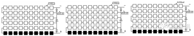
The following 7 different occlusion methods are used.
Among the seven occlusion modes, the occlusion amounts of the scheme 2 and the scheme 6, the scheme 3, and the scheme 7 are substantially the same. What about their output power? Look at the table below.
It can be seen that the output power of scheme 6 is much larger than that of scheme 2, and the output power of scheme 7 is much larger than scheme 3. After the longitudinal shadow is shielded, the diodes are all turned on. In this case, the current of the component is very low, less than 1A; after the horizontally mounted shadow is blocked, only one diode is turned on, and the other two are normal, so the power is reduced. Not big.
4, summary
The solar panels are arranged in a horizontal and vertical direction, and the power generation after receiving the occlusion is reduced as shown in the figure below.


When the solar mounting structure adopts the horizontal layout, the advantage is that the blocked component can still ensure the power generation of the component. The disadvantage is that the installation speed is slower than that of the vertical layout, and the investment of the solar bracket is also increased. Moreover, dust is easily accumulated on the lower edge of the component, and the amount of dust accumulated in the horizontal row is large. When the components are vertically laid out, the vertical layout is easy to install and the investment is less. The disadvantage is that the occlusion causes a large loss of power generation. Investors can choose according to their own project conditions.

Above news from CHIKO Sales & Marketing department
Add: No 680 Xingwen Rd. Jiading dist. Shanghai 201801 China
Phone: +86(21) 59972267 59973712 59973713--811
Fax : +86 (21)59972938
Email: Chiko@Chikolar.com
Website: http://www.chikolar.com


 skype
skype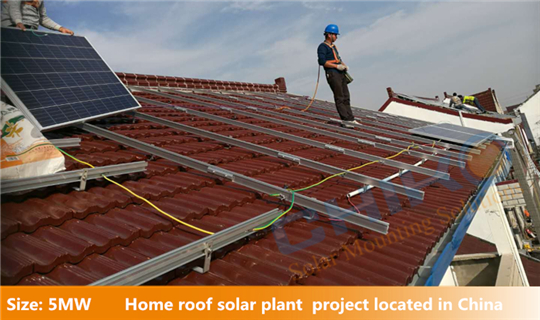
 Plant Gallery