

Learn more about CHIKO commerical and residential mounting solution you can benefit
learn moreFind out which easy solution is just fit for your solar power system
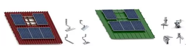
CHIKO Solar designs and manufactures high quality solar mounting systems for pitched roof......learn more>>
Data:2020-04-08

 skype
skype
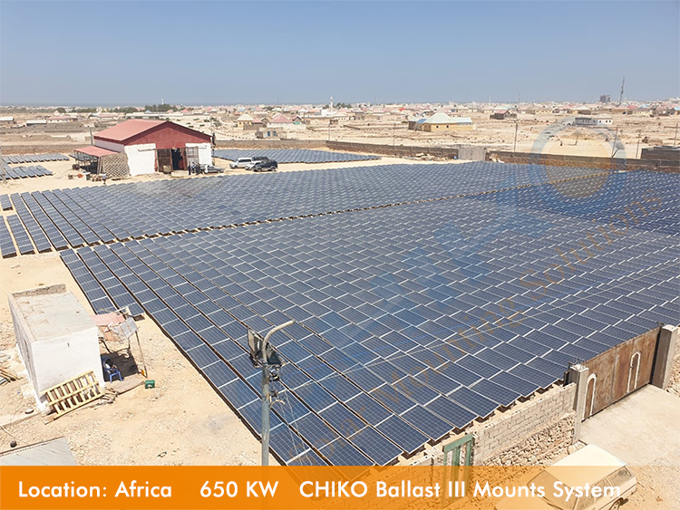
 Plant Gallery